Working process and maintenance & usage connection case of universal valve type A for high-flow oxygen concentrators.

Working process and maintenance & usage connection case of universal valve type A for high-flow oxygen concentrators.
A multi-purpose universal valve based on the replacement function of PHILIPS's integrated maintenance valve as the main focus, while also taking into account the replaceability of pneumatic valves for oxygen concentrators of multiple models.
1.Initial state:
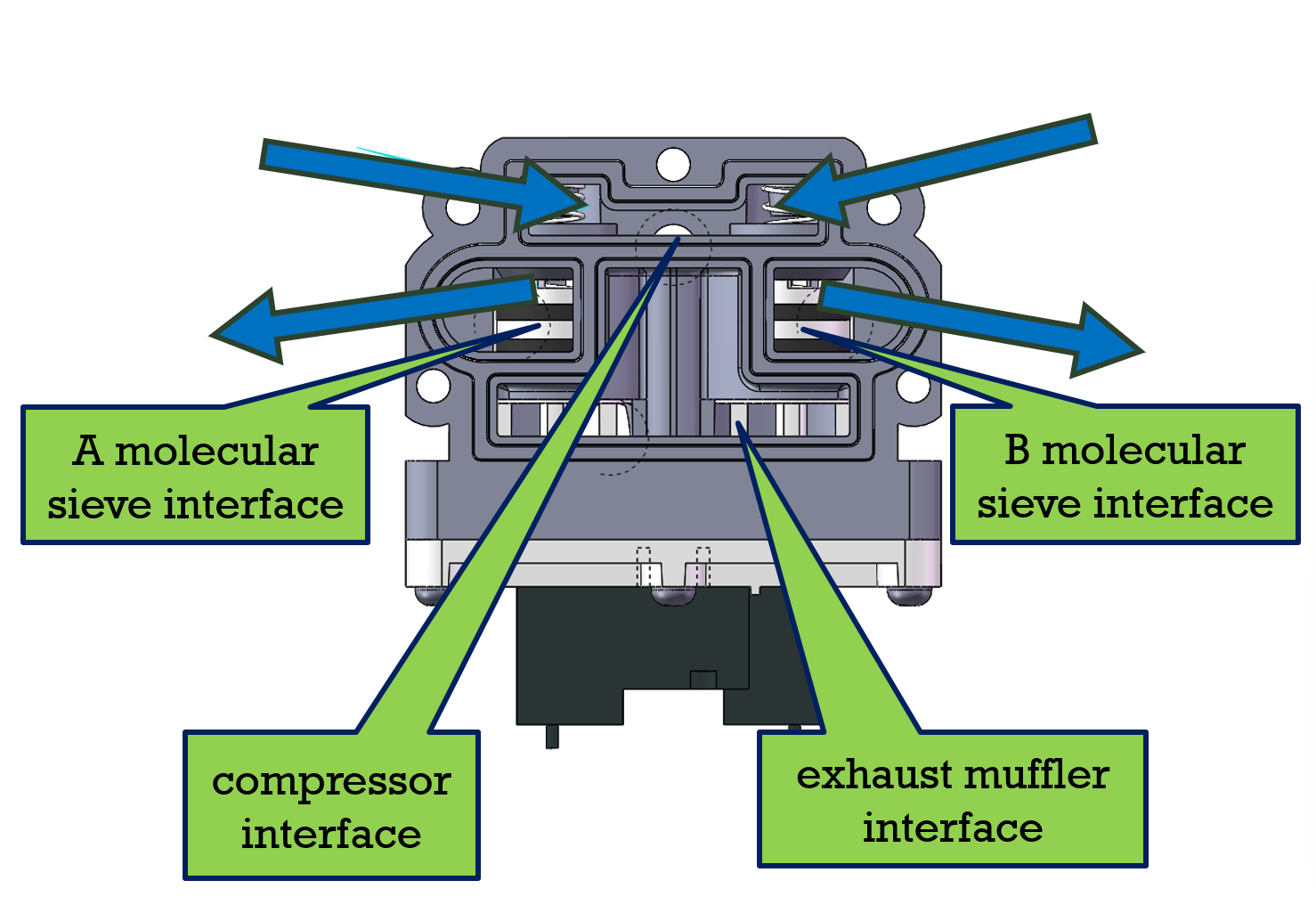
The reverse direction of the blue arrow in the figure is the gas flow direction.
In the initial state, the spring makes the valve core push rod stay on the side close to the solenoid valve. At this time, air is fed into the molecular sieve tube. In this state, turning on the compressor to supply gas will pressurize the two molecular sieve tubes simultaneously, which is used to increase the pressure inside the molecular sieve tube as quickly as possible and increase the adsorption capacity of the molecular sieve, thereby producing high-concentration oxygen.
2.State of supplying oxygen through tube A and desorbing in tube B:
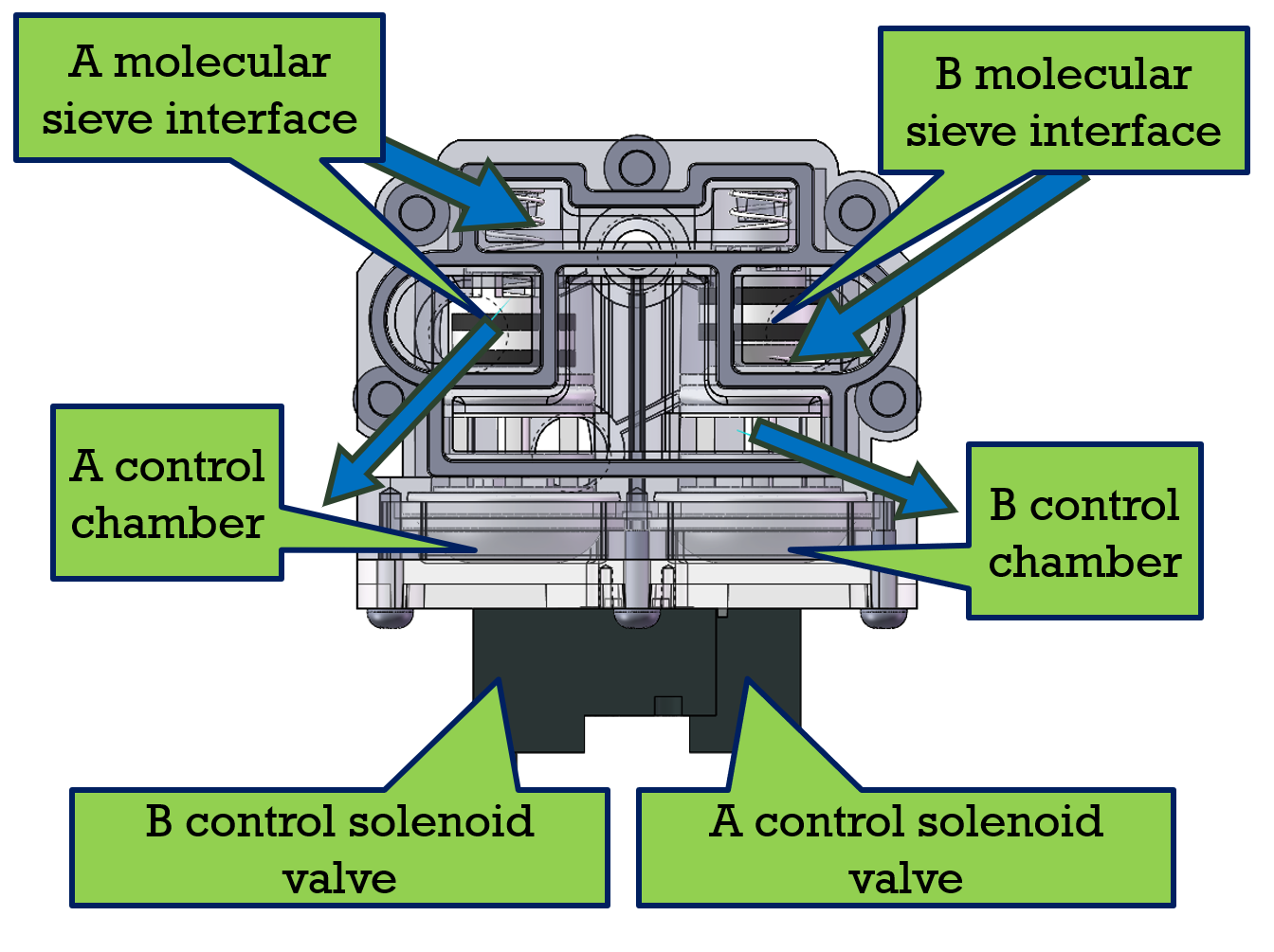
The reverse direction of the blue arrow in the figure is the gas flow direction.
When tube A is supplying oxygen, the solenoid valve of tube B is working. It guides the high-pressure gas to enter the control chamber of tube B and pushes the valve core push rod to stay close to the compressor air inlet. At this time, the molecular sieve tube of tube B exhausts outward. In this state, when the compressor supplies gas to tube A, the molecular sieve tube of tube A will be pressurized, increasing the adsorption capacity of the molecular sieve and thus producing high-concentration oxygen. While tube B quickly exhausts and reduces pressure. Through the purge hole between the two tubes, it obtains some high-concentration oxygen separated from tube A for desorption. After desorption, it can be pressurized again for adsorption.
3.State of supplying oxygen through tube B and desorbing in tube A:
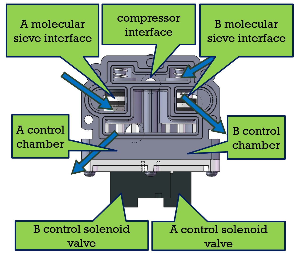
The reverse direction of the blue arrow in the figure is the gas flow direction.
When tube B is in the oxygen supply state, the solenoid valve of tube A operates. It guides high-pressure gas to enter the control chamber of tube A and pushes the valve core push rod to stay close to the compressor. At this time, the molecular sieve tube of tube A exhausts outward. In this state, turning on the compressor to supply gas to tube B will pressurize the molecular sieve tube of tube B, increase the adsorption capacity of the molecular sieve, and thus produce high-concentration oxygen. Meanwhile, tube A quickly exhausts and reduces pressure. Through the purge hole between the two tubes, it obtains some high-concentration oxygen separated from tube B for desorption. After desorption, it can be pressurized again for adsorption.
This cycle continues to form a continuous oxygen supply process.
4.Adjustment during PHILIPS maintenance application.
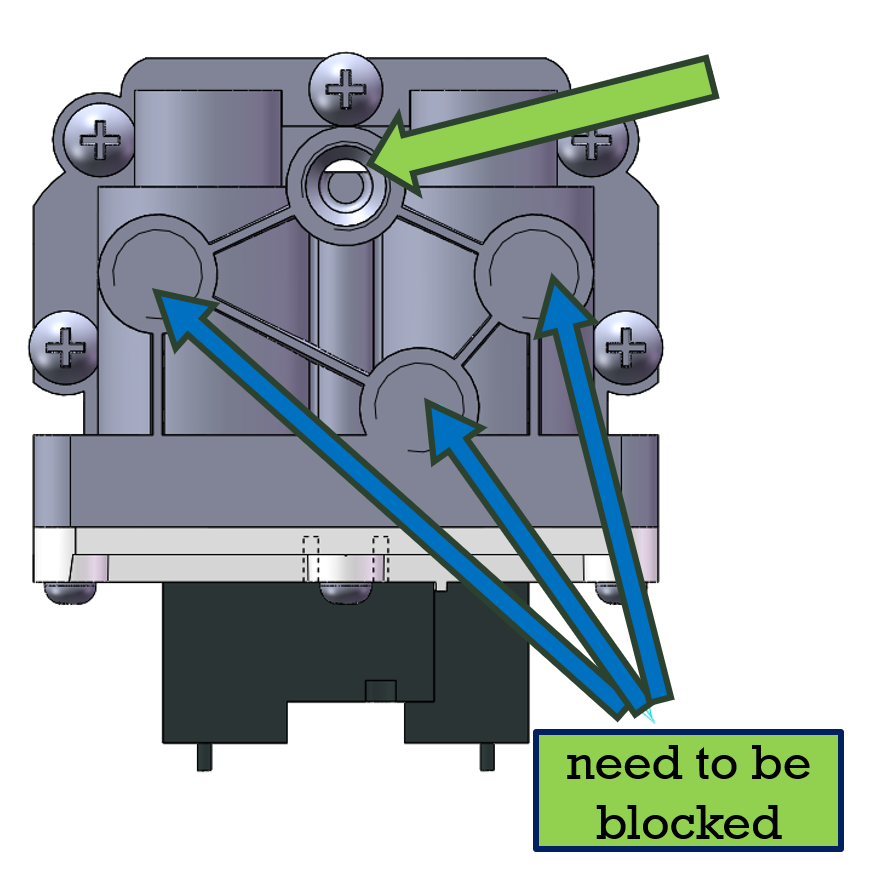
The hole positions indicated by the blue arrows in the figure need to be blocked, while the hole positions indicated by the green arrows are retained.
When applied to PHILIPS molecular sieve, it is necessary to close the air inlet and exhaust interface of tube A and tube B on the back during injection molding. Retain the pressure input port and install an adapter to replace the PHILIPS pressure measurement gas intake port. The specific adapter specification is determined by the inner diameter of the PHILIPS gas intake pipeline.
5.Adjustment during the application of Xinsong Medical OTS.
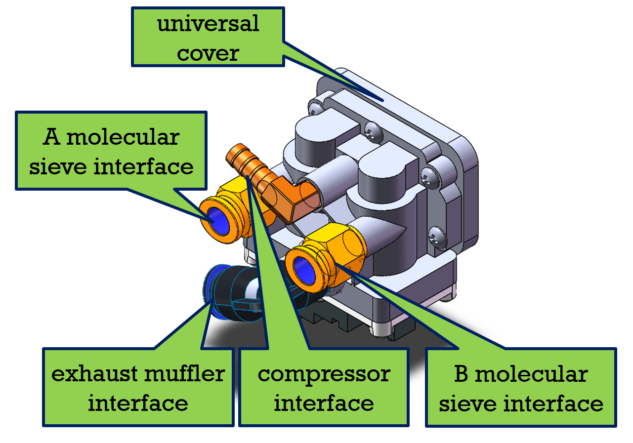
When applied to OTS molecular sieve, a universal cover needs to be added. Seal the PHILIPS transfer interface and install adapters from the four interfaces on the back. The adapters can directly continue to use the previous model to ensure universality.
6.Adjustment during the application of Xinsong Medical MQ.
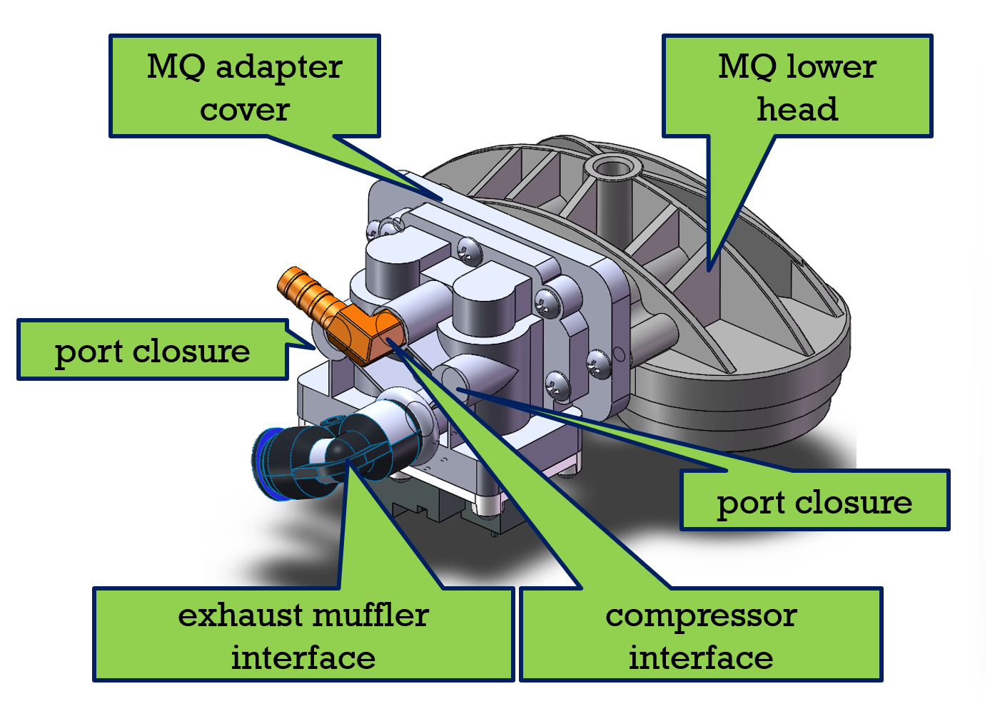
The installation size of MQ conflicts with that of PHILIPS and cannot be simply replaced. If replacement is necessary, the installation holes of the lower head of MQ need to be modified from a spacing of 63mm to a pair of installation holes with a spacing of 76mm. At the same time, when using the MQ adapter cover, the air inlets of tube A and tube B also need to be closed.
Since the modification for MQ replacement is too large and the original valve body cannot be used after modification, there is a relatively high risk. Please make modifications with caution.
