Operation Instruction for Replacing HO-V01 Valve of Perfecto2 After-sales Accessories
Operation Instruction for Replacing HO-V01 Valve
of Perfecto2 After-sales Accessories
1. Fixing
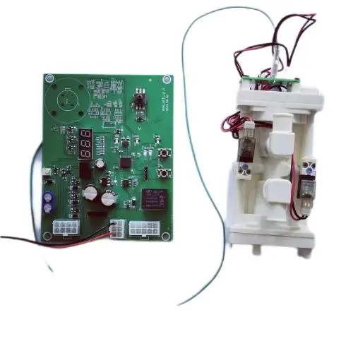
The fixing holes of the control board are fully compatible with the original machine. Just install it according to the original fixing holes.
2. Wiring connection
(1) Insert the A end of the supporting green wire harness into the 8PIN plug of the device. As indicated by the arrows in Figures 1 to 2, it is the second empty pinhole from the top on the left. Pull it outwards slightly with force. It should not be able to be pulled out to ensure that the buckle is snapped into the plug. The B end is connected to the P4 socket in the supporting adapter board as shown in Figure 1.
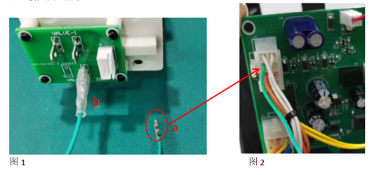
Figure 1 and Figure 2
(2) The interface of the control board connector is compatible with the original circuit board. Just insert the plug at the corresponding position into the corresponding socket directly according to the original machine as shown in Figure 3.
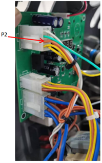
Figure 3
(3) Insert the two orange wires corresponding to the original valve into the P1 and P2 inserts of the adapter board as shown in Figure 4. Note that the directions should correspond. In Figure 4, P2 is the orange wire in the third row from the top on the left in Figure 3. You can use a multimeter in the continuity test gear to confirm.
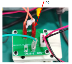
Figure 4
3. Pipeline connection
(1) The pressure detection tube, that is, the pipeline connecting the original control board and the black sensor, is connected to the pressure sensor of the replaced control board, as shown in the following figure:
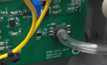
Figure 5
(2) After unplugging the pipeline connected to the white plug, bend it and tie it up with a cable tie as shown in the following figure.
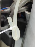
Figure 6
1. Fixing
(1) As shown in the following figure, when the control board is powered on and the "left button" is pressed, the displayed value should be 075. If it is not this value, it can be adjusted by pressing the "left button" and "right button". After 10 seconds, it will automatically jump back to the pressure display state.
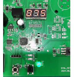
Figure 7
(2) If a new valve body is replaced, when the "right button" is pressed, the displayed value should be 01. If it shows 00, press the "left button" to adjust it to 01.
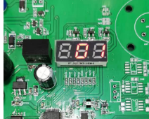
Figure 8
(3) If only the control board is replaced and the valve body is not replaced, the value in the above figure should be 00.
5. Others
The control board is equipped with a high-pressure alarm function. If it is detected that the pressure is higher than the set pressure, it may cause dangers such as pipeline rupture. At this time, turn off the compressor. The yellow indicator light on the front panel is lit, and at the same time, the internal red indicator light is lit.
5. Related Products


